Custom fixtures: repeatability is a stiffness figure before it is an accuracy figure
A fixture that locates a part to 0.05 mm and deflects 0.3 mm under the clamp is a fixture with a 0.3 mm repeatability, and the drawing will not say so.
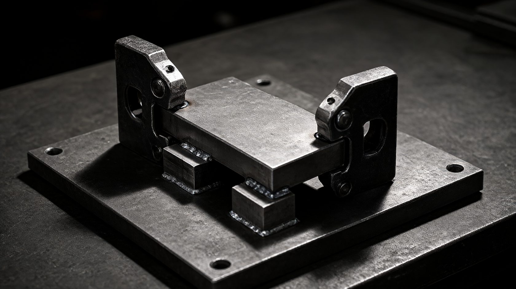
A fixture has three jobs and only one is on the drawing
A welding fixture locates the part, holds it against the process forces and conducts heat away. Most fixture drawings specify only the first, and the other two decide whether the part is the same every cycle.
Locating is a kinematic problem: three points define a plane, two define a line and one defines a point, and any more than six contacts over-constrains the part. An over-constrained fixture distorts the part to fit the fixture.
Holding is a stiffness problem, because the clamp force deflects the part and the fixture. A fixture that is stiff enough for the clamp is a fixture that holds the part where it was located.
Heat conduction is a distortion problem, because a fixture that sinks heat produces a different cooling pattern on the part. A copper backing bar and a steel one produce different welds.
Over-constraint and the part that is bent to fit
A part that is clamped at seven points is a part that is bent until all seven touch, and the bend is locked in by the weld. On release the part springs back to a shape that is neither the part's nor the fixture's.
The symptom is a part that measures correctly in the fixture and out of tolerance after release. The measurement in the fixture was a measurement of the fixture.
The fix is a kinematic location with three pads on a machined datum, two on a second datum and one on a third, plus clamps that push the part onto those pads rather than onto additional contacts.
The specification should state the locating scheme with the datum features, the number of contacts and the clamp directions. A fixture drawing that shows pads but not the datum scheme is a drawing that invites over-constraint.
Stiffness: the deflection that is invisible until it is measured
A fixture deflects under the clamp force, and the deflection is the difference between the fixture's accuracy and the part's repeatability. A fixture built to 0.05 mm that deflects 0.3 mm has a 0.3 mm repeatability.
The deflection is set by the fixture's structure: a plate overhanging a support, a thin riser, a single-sided clamp. Each of those is a spring, and the spring's rate is set by the section and the span.
The measurement is a dial gauge on the part at the point of maximum overhang, with the clamp applied and released. A fixture that moves 0.2 mm under the clamp is a fixture that has to be stiffened before the tolerance can be met.
The specification should state the clamp force, the maximum allowable deflection at the part and the fixture's stiffness figure. A stiffness figure in newtons per millimetre is the only way to check the design before it is built.
The locating pad and the wear that changes the height
A locating pad is a small area that carries the part, and its height is the datum. A pad that wears by 0.05 mm changes the part's position by 0.05 mm and no one measures the pad.
Pads wear fastest where the part slides onto them, and a pad with a sharp edge wears at the edge. A pad with a chamfered edge wears more evenly and lasts longer.
The pads should be replaceable and hardened, and their height should be checked on a count of cycles. A pad that is checked on a schedule is a pad that drifts between checks.
The specification should state the pad material and hardness, the replaceable design and the height check interval. A pad welded into the fixture is a pad that is replaced by rebuilding the fixture.
Clamp force and the panel that bows
A clamp applies a force to hold a part, and on a thin panel the force bows the panel between the clamps. The bow is a gap at the seam and a distortion after release.
The bow is set by the force, the panel thickness and the distance between clamps. A force that is sufficient to hold a thick plate will bow a thin sheet by several millimetres.
The remedy is a distributed clamp, a vacuum table or a lower force with more clamps. Each is a design decision and each changes the fixture's cost.
The specification should state the force per clamp, the clamp spacing and the maximum panel deflection. A clamp force given without a spacing is a force for an unknown span.
Heat conduction and the backing bar
A backing bar under a weld seam conducts heat away and supports the pool. A copper bar conducts fast and produces a narrow heat-affected zone; a steel bar conducts slowly and produces a wider one.
The bar's material also matters for the weld's appearance: a copper bar leaves a smooth root, a steel bar can leave a rougher one. A part that is inspected on the root sees the bar's material.
The bar is a consumable in the sense that it wears and it distorts. A bar that has been heated repeatedly is a bar that has bowed, and a bowed bar is a gap under the seam.
The specification should state the bar material, its flatness and its replacement criterion. A backing bar specified only as a material is a bar that will be used until it is visibly worn.
Tooling plate flatness and the shim stack
A fixture is built on a tooling plate, and the plate's flatness sets the fixture's datum. A plate that is flat to 0.1 mm over a metre and shimmed at the corners is a plate that moves under load.
Shims are a convenient way to set a height and they are a poor way to carry a load. A stack of shims compresses, and the height changes with the clamp force.
The correct approach is a machined pad at the required height, with shims only for adjustment and never for structural support. A shimmed support is a support with a variable height.
The specification should state the plate flatness, the pad machining tolerance and the rule that shims are adjustment-only. A rule that is not written is a rule that the shop will break to save a setup.
Repeatability measured at the part, ten cycles
A fixture's repeatability is measured by loading and unloading the same part ten times and measuring a datum feature on the part, not on the fixture. The difference between the readings is the repeatability.
Ten cycles is enough to see a trend and not enough to characterise a wear pattern. For a new fixture the useful test is a hundred cycles, run once, with a measurement every ten.
The measurement should be at the part's datum and at the feature that the next process uses, because a fixture can be repeatable at one feature and not at another.
The specification should state the number of cycles, the feature measured and the acceptance. A repeatability figure without a feature is a figure for a different part of the fixture.
Changeover: the fixture that gets re-shimmed
A fixture that is changed over between part variants is a fixture whose datum is re-established on every changeover. A changeover that relies on shims is a changeover that drifts.
The drift is usually in one direction, because the operator adds a shim and never removes one. A fixture that has been changed over fifty times is a fixture with fifty shims.
The fix is a set of interchangeable inserts with machined heights, or a fixture with a locking datum that is verified after each changeover. Both are design decisions.
The specification should state the changeover method and the datum verification after changeover, with the acceptance. A changeover procedure without a verification is a procedure that assumes the operator is consistent.
A fixture specification in eight lines
Eight lines cover a custom fixture: locating scheme with datum features and the number of contacts, clamp force per clamp with spacing and maximum part deflection, fixture stiffness in newtons per millimetre with allowable deflection, pad material, hardness and height check interval, backing bar material with flatness and replacement criterion, tooling plate flatness with the shims-for-adjustment rule, repeatability at a named part feature over a stated cycle count, and the changeover method with a datum verification.
The lines describe stiffness and datum as much as geometry, which is what a fixture is. A fixture drawing that gives only dimensions has given the shape and not the function.
The two lines that decide whether the tolerance is met are the stiffness figure and the repeatability at a named feature, because both are invisible on a drawing and both are measurable before shipment.
Write the eight, run a hundred-cycle repeatability test on the first fixture, and re-check the pads when the part's datum changes. A new datum is a new fixture.
The fixture whose stiffness is given in newtons per millimetre is the customized welding fixtures, and that figure is the only way to check a tolerance before the fixture is built.
- 01Locating scheme with datum features and the number of contacts, six maximum.
- 02Clamp force per clamp, clamp spacing and maximum allowable part deflection.
- 03Fixture stiffness in newtons per millimetre, with the allowable deflection at the part.
- 04Pad material and hardness, replaceable design, height check interval.
- 05Backing bar material with flatness and replacement criterion.
- 06Tooling plate flatness, with shims allowed for adjustment only and never for support.
- 07Repeatability measured at a named part feature over a stated cycle count.
- 08Changeover method with a datum verification and an acceptance after each change.