Floor tracks: the robot's accuracy is decided by the slab under it
A seventh-axis track extends a robot's reach by metres. The straightness of the rail, not the robot's repeatability, sets the accuracy at the far end.
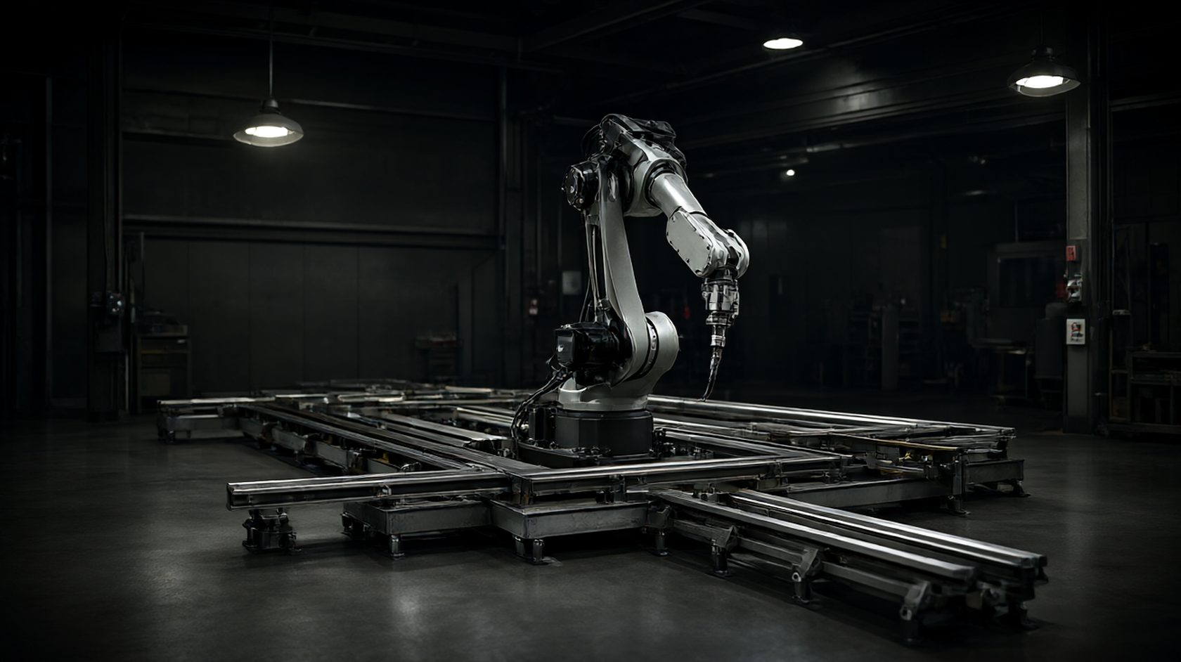
A track is a robot axis that nobody calibrates
A floor track carries a robot or a positioner along a line, and it adds a travel axis whose repeatability is often worse than the robot's. The robot is calibrated to a tenth of a millimetre; the track is installed to a millimetre and never checked again.
The consequence is that the accuracy of a weld or a pick depends on where along the track it happens. A cell that is accurate at the home position drifts at the far end, and the drift is attributed to the robot.
The track's contribution is a straightness error and a level error, and both are fixed at installation. Neither can be corrected by a software offset at the far end without making the home end wrong.
So a track specification is an installation specification, and its acceptance criteria belong in the civil works rather than in the robot commissioning.
The slab, the anchors and the settlement that happens later
A track is anchored to a slab, and the slab moves. A new slab settles, a floor with a heated screed expands, and a slab over a basement deflects under load. Each of those moves the rail.
The anchors are the interface, and a mechanical anchor in a thin slab pulls out under the lateral load of a moving carriage. A chemical anchor in a clean hole holds better, and both need a slab thick enough to develop the load.
The usual failure is not a pull-out but a settlement of a few millimetres over the first year, which is enough to change the level and to load the carriage unevenly. A track that was level at commissioning is not level at the first service.
The specification should state the slab thickness, the anchor type and the minimum cure before loading, plus a re-level check at a stated interval after installation.
Straightness: the figure that matters and how it is measured
Straightness is measured as a deviation from a straight line over a stated length, and the length matters as much as the value. A track straight to 0.5 mm over a metre can be 3 mm out over ten metres if the error accumulates.
The measurement is a laser tracker, a taut wire with a scale, or a dial gauge on a carriage run along the rail. A dial gauge on the carriage is the practical method on site and it measures the error the robot will see.
The error has two components: a uniform bow, which can be compensated by a software lookup, and a local kink, which cannot. A kink at a joint is the defect that produces a step in the weld.
The specification should give straightness over the full travel and a local limit between any two points a metre apart. A single figure over the full length allows a kink that passes the average.
Level and the two rails that must be parallel
A track with two rails has a level error across the pair and a parallelism error along it. A cross-level error tilts the carriage; a parallelism error loads the bearings and produces a rumble.
The cross-level tolerance is usually tighter than the longitudinal one, because a tilt is not compensable and it loads one side of the carriage. A track that is level along its length and twisted across it wears its rollers.
The two rails are set from a common datum and checked as a pair, not individually. A rail that is straight to itself and offset from its partner produces a carriage that binds at one end.
The specification should state the cross-level, the parallelism and the datum from which both are set. A tolerance without a datum is a number that no surveyor can apply.
Joints, steps and the carriage that feels them
A track longer than a standard rail has joints, and every joint is a potential step and a potential kink. A step of 0.1 mm at a joint is felt through the carriage as a knock and appears in the weld as a mark.
The joint is set by a machined end and a dowel, or by a splice plate and a shim. A joint that is bolted without a dowel relies on friction and moves under load.
The joint should be positioned away from the working zone, so the step occurs in a region where the robot is not welding. A joint in the middle of the weld is a step in the middle of the bead.
The specification should state the joint type, the maximum step and the joint positions relative to the working zones. A joint position is a layout decision and it belongs on the drawing.
Rack, pinion and the backlash that appears at speed
A track is driven by a rack and pinion or by a friction drive, and both have a backlash that grows with wear. A backlash of 0.2 mm is invisible at low speed and produces a hesitation at reversal.
The rack is bolted to the rail and its pitch error adds to the rail's straightness error. A rack with a pitch error of 0.1 mm per metre produces a position error that a linear scale would reveal and an encoder on the motor would not.
The drive should be referenced to a linear scale on the rail rather than to a motor encoder, because the scale measures the carriage and not the motor. A motor encoder measures the pinion, and the pinion is not the tool.
The specification should state the drive type, the backlash limit and whether a linear scale is fitted. A track without a scale is a track whose position accuracy is an assumption.
Cable and hose management: the failure that stops the cell
A moving carriage drags cables and hoses, and the management of those is the most common cause of a stopped cell. A cable that is dressed wrong fatigues at the bend and fails at the conductor.
The two options are a festoon and a cable chain. A festoon is cheaper and suited to long travel; a chain is more compact and requires a bend radius than the cable can survive.
The bend radius is the specification that matters, and it is set by the cable rather than by the chain. A chain with a radius tighter than the cable's rating is a chain that shortens the cable's life by a factor.
The specification should state the management type, the bend radius and the cable's flex rating, plus a cable count check at each service. A cable failure is a maintenance item, not an accident.
Foundation isolation and the machine next door
A track is sensitive to vibration from a press or a shear nearby, and the sensitivity shows as a weld that varies with the other machine's cycle. The vibration enters through the slab and reaches the tool.
The remedies are isolation, distance and scheduling. Isolation is a damped pad or a separate plinth; distance is a layout decision; scheduling is a control decision that runs the press when the robot is not welding.
The measurement is a vibration survey at the track with the other machine running, recorded as a velocity at the frequencies that matter. A survey without the other machine running measures nothing.
The specification should state the allowable vibration at the track and the isolation if it is needed. A track specified without a vibration limit is a track specified for a quiet building.
Commissioning: what to measure and in what order
The commissioning sequence is slab check, anchor cure, rail straightness, cross-level and parallelism, joint step, rack pitch, drive backlash, then scale calibration. Each step depends on the one before, and skipping one invalidates the next.
A rail surveyed before the anchors have cured is a rail that will move. A scale calibrated before the backlash is set is a scale that measures a moving target.
The record should be a table of measurements at stated positions along the travel, not a single pass or fail. A table shows the trend and the trend predicts the drift.
The specification should name the instrument, the positions and the acceptance for each step, and should require the table in the handover file. A handover without a table is a handover without evidence.
A floor track specification in nine lines
Nine lines cover a floor track: slab thickness and anchor type with cure time, straightness over full travel plus a local limit per metre, cross-level and parallelism from a named datum, joint type with maximum step and joint positions, drive type with backlash limit, linear scale fitted or not, cable management with bend radius, allowable vibration, and the commissioning table with its positions and instruments.
The lines are civil, mechanical and control lines in one document, which is what a track is. A track specification that is only mechanical leaves the accuracy to the electrician.
The two lines that decide the far-end accuracy are the local straightness limit and the linear scale, because those are the two that a full-travel average will hide.
Write the nine, keep the commissioning table, and re-survey after the first year. A slab settles and a track that was accepted at commissioning is a track that has moved.
A track specified with a local straightness limit as well as a full-travel figure is the welding positioner floor track, and the local limit is what prevents a kink at a joint.
- 01Slab thickness, anchor type and cure time before loading stated.
- 02Straightness over full travel plus a local limit between any two points a metre apart.
- 03Cross-level and parallelism measured from a named datum.
- 04Joint type with maximum step, and joint positions away from working zones.
- 05Drive type with a backlash limit, measured at reversal.
- 06Linear scale on the rail rather than a motor encoder alone.
- 07Cable management type with a bend radius at or above the cable's flex rating.
- 08Vibration survey run with the neighbouring machine running, not with it stopped.