MIG/MAG on a robot: the transfer mode is the parameter, not the wire feed number
Two welders with the same wire feed and the same voltage can run different transfer modes, and only one of them is stable at the joint in front of the robot.
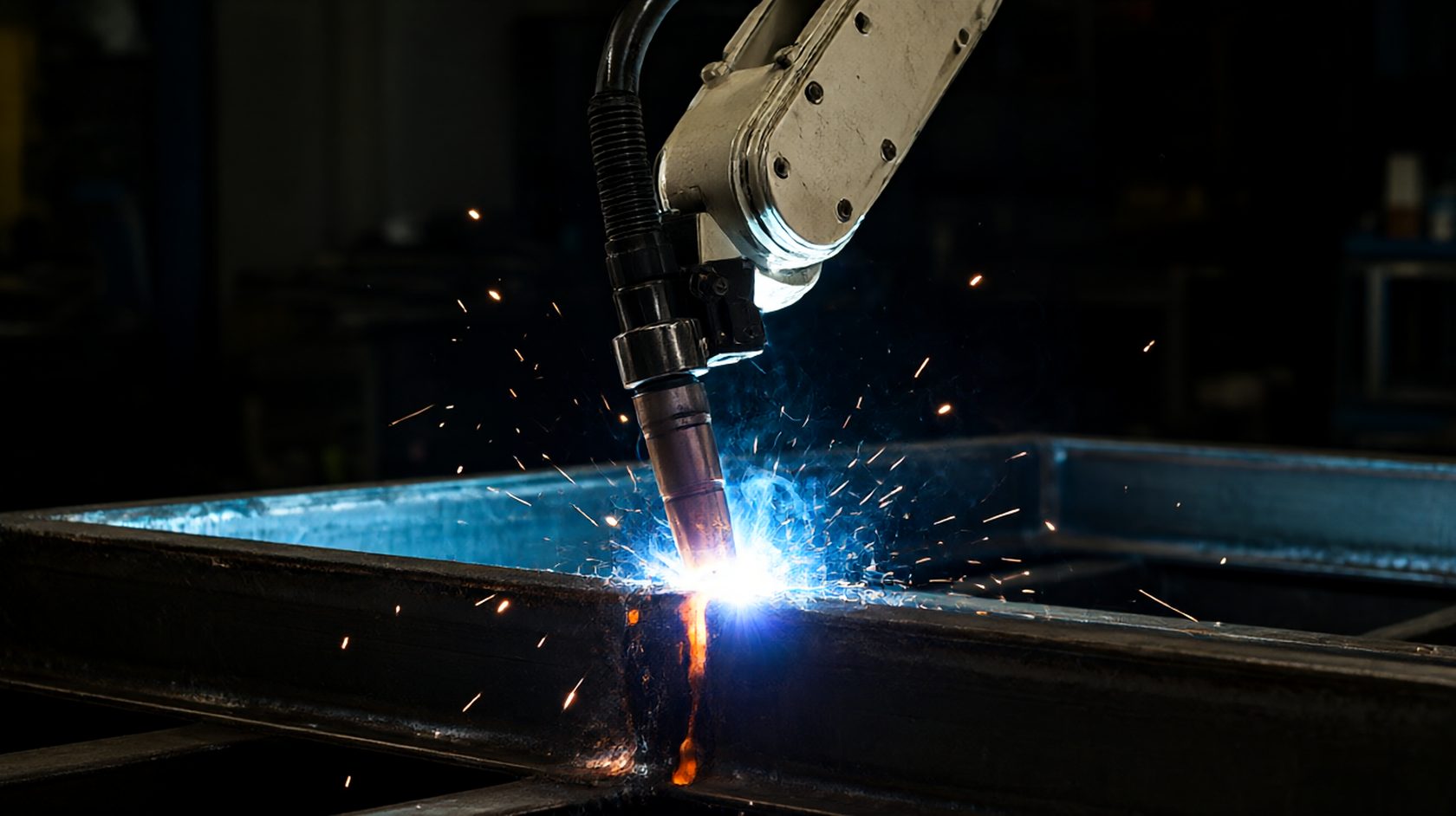
Three modes, one dial
A MIG/MAG power source offers short-circuit, globular and spray transfer, and modern inverters add pulsed variants of each. The mode is set by the relationship between voltage, wire feed and inductance, not by any single number on the panel.
Short-circuit transfer runs at low voltage and low current, and the metal transfers by touching the pool and pinching off. It is stable at low heat input and it is the mode for thin sheet and for out-of-position work.
Spray transfer needs a current above a transition value that depends on the wire and the shielding gas, and it transfers as a stream of fine droplets. It is stable, deep and hot, and it is unsuitable for thin sheet and for vertical work.
Globular sits between them and is the mode nobody should choose: large droplets, an unstable arc and spatter. A robot that appears to run globular is a robot whose parameters are in the transition zone.
The transition current is a property of the consumable
The current at which short-circuit becomes spray depends on the wire diameter, the alloy and the shielding gas, and it moves with all three. A 1.2 mm mild steel wire in an argon-rich mix transitions around two hundred amps; a 1.0 mm wire transitions lower.
That means a parameter set is not portable between wire sizes. A programme written for 1.2 mm run on a 1.0 mm spool will be in a different mode at the same wire feed, and the arc will sound wrong before the weld looks wrong.
The transition also moves with the gas: a CO2-rich mix raises the transition current and keeps the arc in short-circuit longer. A shop that switches gas to save cost changes the mode of every programme it owns.
The specification should name the wire diameter, the alloy and the gas mix, and should record the current at which the mode changes for that combination. Without those, a parameter sheet is a set of numbers with no meaning.
Pulsed transfer and the heat input you can actually control
Pulsed transfer alternates a peak current above the transition and a background current below it, so the average current can be low while the droplets detach in spray. That decouples heat input from detachment, which is the whole reason pulsed mode exists.
The two settings that matter are the pulse frequency and the pulse width, and together they set the droplet per pulse. A one-drop-per-pulse condition is the most stable, and it is reached by matching the frequency to the wire feed.
A frequency too low gives several droplets per pulse and a ragged arc; too high gives a droplet every second or third pulse and an arc that stutters. The audible signature of one-drop-per-pulse is a steady buzz rather than a hiss or a crackle.
The consequence for a robot is that the heat input can be held constant while the travel speed changes, which is what makes a pulsed programme usable across a family of parts. A short-circuit programme cannot do that, because its heat input is tied to the wire feed.
Inductance and the pinch that decides spatter
In short-circuit transfer, inductance controls how fast the current rises when the wire touches the pool. Low inductance gives a fast rise, a violent pinch and spatter; high inductance gives a softer pinch and a smoother transfer.
The setting is a compromise: too much inductance and the arc is soft and the penetration shallow, too little and the pool is agitated. The correct value is the one that produces a consistent bacon-frying sound rather than a crackle.
On a robot the inductance has a second role, because the torch is at a fixed angle and the wire stub changes as the joint closes. A setting that is right at the start of a seam can be wrong at the end if the fit-up closes the gap.
The practical specification is a spatter count on a test plate rather than an inductance number, because the number is power-source specific. Two machines from different makers at the same nominal inductance behave differently.
Shielding gas and the mode it forces
The shielding gas sets the transition current, the arc shape and the penetration profile, and it is the parameter most often changed without a re-qualification. A switch from a 82/18 argon-CO2 mix to a 92/8 mix raises the transition and changes the bead profile.
CO2 gives a deep finger penetration and a stable short-circuit arc, and it is cheap. Argon-rich mixes give a smoother spray arc and a wider bead, and they cost more per cubic metre.
A helium addition is used for high-heat-input work and for copper, and it changes the arc physics rather than only the chemistry. A shop that adds helium to fix a penetration problem has changed the mode and not only the gas.
The gas flow rate matters as much as the composition, and it should be set with a flow meter at the torch rather than at the regulator. A rate below about twelve litres per minute at the nozzle invites porosity in a draught.
Fit-up, gap and the arc that cannot bridge
A robot welds what it is given, and a gap wider than the arc can bridge produces a bead that looks welded and is not fused. The gap tolerance belongs on the fixture drawing, not on the welding procedure.
The bridgeable gap depends on the mode: spray transfer bridges a wider gap than short-circuit, because the arc is stiffer and the pool is larger. A programme moved from spray to short-circuit loses gap tolerance without anyone noticing.
The usual failure is a gap that opens progressively along a seam, so the first third is sound and the last third is unfused. A destructive test at the start of the seam passes and the part fails in service.
The specification should state the gap range, the mismatch allowance and the tack pattern, and should test at the worst point of the seam rather than at a random point.
Torch angle, stick-out and the two millimetres nobody records
Wire stick-out is the distance from the contact tip to the workpiece, and it changes the current for a given wire feed. A stick-out of fifteen millimetres and one of twenty-five produce different currents from the same programme.
On a robot the stick-out is set by the tool centre point and the contact tip, and it drifts when a tip wears, when a torch is re-clamped, or when a fixture is shimmed. The drift is invisible and it changes the weld.
The torch angle matters for the same reason: a push angle gives a wider, flatter bead and less penetration; a drag angle gives a narrower, deeper bead. A robot programmed with a push angle and re-taught with a drag angle is a different process.
Both belong on the procedure: stick-out with a tolerance, and the angle in two planes. A procedure that gives only volts and amps has described a third of the setup.
Wire feed, liners and the drift that looks like a parameter problem
A wire feeder delivers a set feed rate only if the liner, the drive rolls and the spool are in condition. A worn liner adds friction and the actual feed falls, which reads as a cold weld at unchanged settings.
The drift is gradual and it is blamed on the programme. A shop that re-tunes the programme to compensate for a worn liner ends up with a programme that is correct for a worn liner and wrong for a new one.
The liner should be replaced on a count of wire metres rather than on a failure, and the drive roll pressure checked at the same interval. Both are maintenance items and both should appear in the procedure's notes.
The check is a wire feed calibration against a measured length, run at the start of each shift. A feeder that delivers within two per cent is a feeder whose programme can be trusted.
Monitoring: what a robot can see and what it cannot
A welding robot with arc monitoring can measure current, voltage and wire feed, and it can detect a loss of arc, a short circuit or a gas failure. It cannot see fusion, and fusion is the defect that matters.
The monitoring is therefore a process check rather than a quality check. It catches the events that produce a bad weld, and it does not certify a good one.
The useful addition is a through-arc seam tracking sensor, which follows the joint and reports the deviation. A robot with tracking holds the stick-out and the angle, which is what the fusion depends on.
The specification should name the monitored parameters and the reaction to each out-of-range event, plus the tracking sensor if one is fitted. A monitor without a reaction is a data logger.
A MIG/MAG procedure in nine lines
Nine lines carry a robotic MIG/MAG procedure: wire diameter, alloy and gas mix, transfer mode with the current at which it changes, pulse frequency and width if pulsed, inductance or its equivalent, gap range and mismatch allowance, stick-out with a tolerance, torch angle in two planes, and wire feed calibration interval.
The lines describe a process rather than a machine setting, which is what a procedure is. A setting sheet that lists only volts and amps is a recipe without a method.
The three lines that decide the defect rate are the gas mix, the gap range and the stick-out, because those are the three that drift without a record.
Write the nine, qualify on the worst joint in the family, and re-qualify when the gas, the wire or the fixture changes. Each of those three moves the mode.
A cell whose procedure names the transfer mode with the current at which it changes is the Yaskawa MIG/MAG welding robot, and that single number is what a wire or gas change invalidates.
- 01Transfer mode named, with the current at which it transitions for that wire and gas.
- 02Wire diameter, alloy and gas mix all stated on the procedure.
- 03Pulse frequency and width given if pulsed; one-drop-per-pulse confirmed by ear and bead.
- 04Inductance or its equivalent specified, with a spatter count on a test plate.
- 05Gap range and mismatch allowance on the fixture drawing, not only on the welding procedure.
- 06Stick-out stated with a tolerance; contact tip wear checked on a count.
- 07Torch angle stated in two planes, with push or drag named.
- 08Wire feed calibrated against a measured length at the start of each shift.